为机器人配置传感器#
机器人可以携带传感器进行环境感知。IR-SIM 提供 2D 激光雷达(lidar2d)、简化的 2D FMCW 激光雷达(fmcw_lidar2d,每条光束附带径向速度)和接触传感器(contact2d,用于 contact 碰撞模式),以及可选的视场(FOV)区域;它们都在 YAML 文件中按对象进行配置。本页展示如何配置它们并调节噪声。
LiDAR 配置参数#
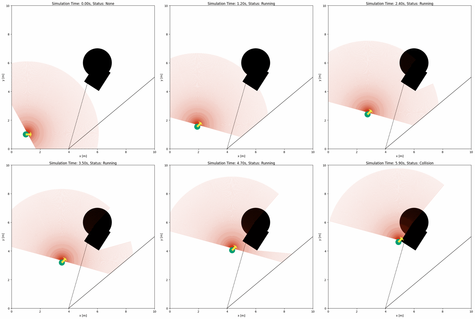
下面的 YAML 配置与 Python 脚本展示了带 2D LiDAR 传感器的机器人示例:
import irsim

env = irsim.make()

for i in range(1000):
    env.step()
    env.render(0.05)

    if env.done():
        break

env.end()
与 Python 脚本同名的 YAML 文件:
world:
  height: 10
  width: 10
  step_time: 0.1
  sample_time: 0.1
  offset: [0, 0]
  collision_mode: 'stop'
  control_mode: 'auto'

robot:
  - kinematics: {name: 'diff'}
    shape: {name: 'circle', radius: 0.2}
    state: [1, 1, 0]
    goal: [9, 9, 0]
    behavior: {name: 'dash'}

    sensors:
      - name: 'lidar2d'
        range_min: 0
        range_max: 5
        angle_range: 3.14
        number: 200
        noise: False
        std: 0.2
        angle_std: 0.01
        offset: [0.1, 0.1, 0.5]
        plot:
          alpha: 0.3

obstacle:
  - shape: {name: 'circle', radius: 1.0, center: [1, 1]}
    state: [5, 5, 0]
    unobstructed: True

  - shape: {name: 'rectangle', length: 1.5, width: 1.2}
    state: [6, 5, 1]

  - shape: {name: 'linestring', vertices: [[10, 5], [4, 0]]}
    state: [0, 0, 0]

  - shape: {name: 'linestring', vertices: [[4, 0], [6, 7]]}
    state: [0, 0, 0]
    unobstructed: True
    plot:
      obj_linestyle: '--'
小技巧
更新顺序
环境会在所有对象完成该时间步移动后再更新传感器,从而避免读数的时间偏差。若手动控制对象,请在 ObjectBase.step(...) 中传入 sensor_step=True,或在更新对象状态后调用 obj.sensor_step()。
关键参数说明#
若要配置 2D LiDAR,需在机器人 sensors 部分定义名为 lidar2d 的传感器。主要参数如下:
range_min:激光束的最小量程。比它更近的回波按
range_min报告:该光束视为被遮挡,但不携带测量值。range_max:激光束的最大量程。
angle_range:激光束覆盖的角度范围。完整的 360 度扫描可在 YAML 中使用
6.283185,或在 Python 中使用2 * pi。number:束数量。
alpha:激光束透明度。
完整参数列表见 YAML 配置。
带噪声的高级 LiDAR 配置#
若需为 LiDAR 添加噪声,可将 noise 设为 True。
import irsim

env = irsim.make()

for i in range(1000):
    env.step()
    env.render(0.05)

    if env.done():
        break

env.end()
world:
  height: 10
  width: 10
  step_time: 0.1
  sample_time: 0.1
  offset: [0, 0]
  collision_mode: 'stop'
  control_mode: 'auto'

robot:
  - kinematics: {name: 'diff', noise: True, alpha: [0.1, 0, 0, 0.3]}
    shape: {name: 'circle', radius: 0.2}
    state: [1, 1, 0]
    goal: [9, 9, 0]
    behavior: {name: 'dash', wander: True}

    plot:
      show_trajectory: True

    sensors:
      - type: 'lidar2d'
        range_min: 0
        range_max: 5
        angle_range: 3.14
        number: 200
        noise: True
        std: 0.1
        angle_std: 0.01
        offset: [0, 0, 0]
        alpha: 0.3

obstacle:
  - shape: {name: 'circle', radius: 1.0}
    state: [5, 5, 0]
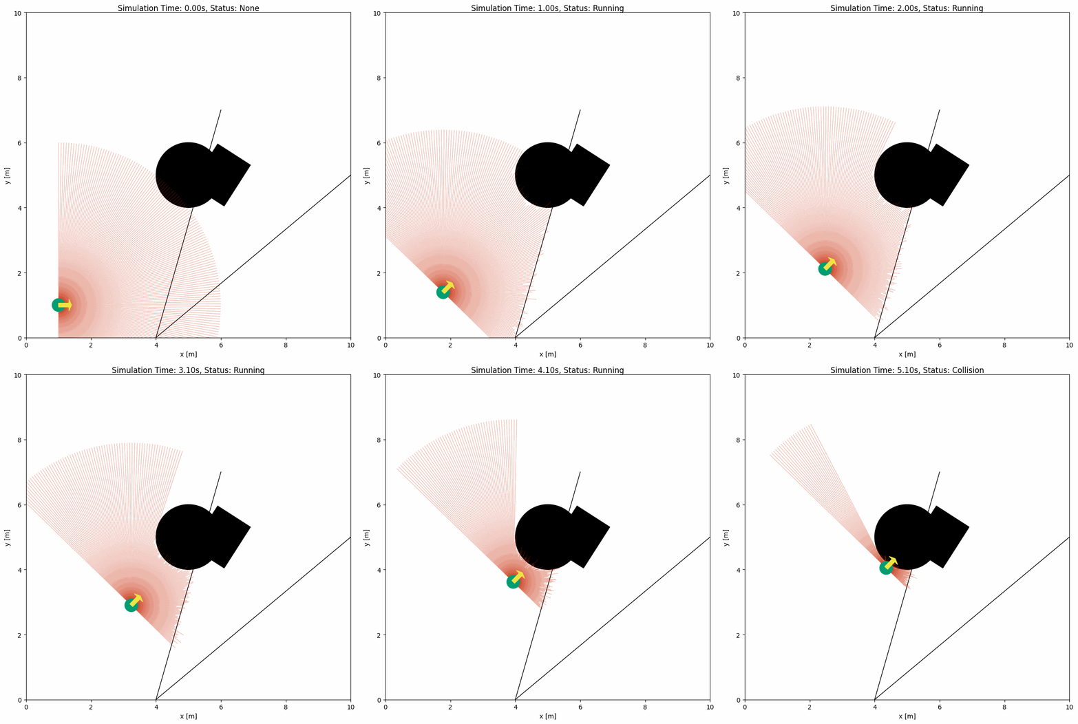
高斯噪声只加在击中物体的光束上:std 是距离噪声的标准差,angle_std(默认 0,即关闭)是每条光束方向噪声的标准差。带噪声的距离保持在 [range_min, range_max] 内,被推到 range_max 之外的击中会变成未命中,未命中的光束保持 range_max 且不加噪声。
量程约定。 未击中任何物体的光束读数为 range_max,这也是 Isaac Sim 的 LaserScan 桥接所发布的值,因此 ranges 对学习流水线始终是有限值。get_scan()["valid"] 标记有可用回波的光束:距离位于 [range_min, range_max] 内的击中。未命中以及盲区内的回波为无效,后者读数为 range_min,因此该光束仍视为被遮挡;get_points() 只把有效光束转换为点。env.get_msg() 返回的 ROS 风格 LaserScan 默认携带同样的有限距离,因此用于学习的快照不受影响;env.get_msg(use_inf=True) 则遵循 REP 117(与 Gazebo 一致):无回波为 +inf,距离过近无法测量的回波为 -inf。
FMCW 激光雷达配置参数#
IR-SIM 还提供了一个简化的 2D FMCW 激光雷达传感器,名为 fmcw_lidar2d。它保持与标准 2D 激光雷达相同的光束几何结构,但每条有效光束会额外返回一个标量 radial_velocity(径向速度)测量值。这便于演示多普勒测量如何帮助理解动态障碍物。valid 标记距离位于 [range_min, range_max] 内的光束;比 range_min 更近的回波按 range_min 报告并保持无效,因此该光束仍视为被遮挡。
下方示例使用一个静止的传感器主体,朝前方覆盖 120 度视场,并设置了多个移动障碍物。开启绘图后,有效回波会按径向速度着色,并在端点处标记出来。
import irsim

env = irsim.make("fmcw_lidar_world.yaml")

for step in range(120):
    env.step()

    scan = env.get_lidar_scan()
    valid_count = int(scan["valid"].sum())
    valid_indices = scan["valid"].nonzero()[0]
    if len(valid_indices) > 0:
        beam_idx = max(valid_indices, key=lambda idx: abs(scan["radial_velocity"][idx]))
        print(
            f"step={step:03d} valid_beams={valid_count:03d} "
            f"beam={beam_idx:03d} range={scan['ranges'][beam_idx]:.3f} "
            f"radial_velocity={scan['radial_velocity'][beam_idx]:.3f}"
        )
    else:
        print(f"step={step:03d} valid_beams={valid_count:03d} no valid returns")

    env.render(0.05, mode="all")

env.end(3)
world:
  height: 10
  width: 10
  step_time: 0.1
  sample_time: 0.1
  offset: [0, 0]
  collision_mode: 'stop'
  control_mode: 'auto'

robot:
  - kinematics: {name: 'diff'}
    shape: {name: 'circle', radius: 0.2}
    state: [2.0, 5.0, 0.0]
    goal: [20.0, 5.0, 0.0]
    vel_min: [-2, -2.0]
    vel_max: [2, 2.0]
    behavior: {name: 'dash'}
    static: true

    sensors:
      - type: 'fmcw_lidar2d'
        range_min: 0.0
        range_max: 8.0
        angle_range: 2.0944   # 120 degrees
        number: 121           # approximately 1 degree per beam, including center beam
        motion_compensate: False
        noise: False
        offset: [0.0, 0.0, 0.0]
        plot:
          alpha: 0.8
          velocity_linewidth: 2.0
          no_hit_linewidth: 0.25
          no_hit_alpha: 0.01
          show_velocity_markers: True
          velocity_marker_size: 45
          velocity_marker_edge_color: 'black'
          velocity_marker_edge_width: 0.5
          velocity_color_max: 0.6

obstacle:
  - kinematics: {name: 'omni'}
    shape: {name: 'circle', radius: 0.25}
    state: [8.0, 5.0, 0.0]
    goal: [3.0, 5.0, 0.0]
    vel_min: [-0.8, -0.8]
    vel_max: [0.8, 0.8]
    behavior: {name: 'dash'}
    plot: {show_goal: True}

  - kinematics: {name: 'omni'}
    shape: {name: 'circle', radius: 0.22}
    state: [7.5, 6.8, 0.0]
    goal: [3.2, 4.8, 0.0]
    vel_min: [-0.4, -0.4]
    vel_max: [0.4, 0.4]
    behavior: {name: 'dash'}
    plot: {show_goal: True}

  - kinematics: {name: 'omni'}
    shape: {name: 'circle', radius: 0.20}
    state: [8.6, 3.8, 0.0]
    goal: [3.5, 5.6, 0.0]
    vel_min: [-1.2, -1.2]
    vel_max: [1.2, 1.2]
    behavior: {name: 'dash'}
    plot: {show_goal: True}

  - kinematics: {name: 'omni'}
    shape: {name: 'circle', radius: 0.24}
    state: [6.8, 7.6, 0.0]
    goal: [4.6, 6.4, 0.0]
    vel_min: [-0.2, -0.2]
    vel_max: [0.2, 0.2]
    behavior: {name: 'dash'}
    plot: {show_goal: True}
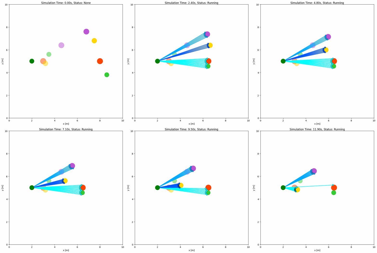
FMCW 专用关键参数:
motion_compensate:是否从测量的径向速度中扣除自身运动分量。
velocity_noise_std:施加在
radial_velocity上的高斯噪声标准差。
可视化参数位于传感器的 plot: 子字典下(与 lidar2d 及对象的 plot: 一致);为保持向后兼容,扁平的顶层键仍然被接受:
velocity_color:绘图时是否按径向速度对有效光束着色。
velocity_color_max:绘图颜色达到饱和的速度幅值。
返回的扫描数据保留了标准激光雷达的角度元数据,并新增以下字段:
radial_velocity:每条光束的标量径向速度。
valid:该光束是否在
range_max范围内有有效回波。
完整可运行示例位于 usage/22fmcw_lidar_world/。
接触传感器配置参数#
在 collision_mode: 'contact' 下,每个对象都自带一个接触传感器 obj.contact,由接触求解器每步写入,因此其读数始终可用:obj.contact.in_contact、obj.contact.partners、obj.contact.reports(每个接触一条报告,含 other、point、normal、depth 和 force)、obj.contact.force、obj.contact.contact_time、obj.contact.air_time、obj.contact.started 和 obj.contact.ended。接触模型的计算内容见配置机器人和障碍物中的 Physical Properties and Contact Mode 一节。
在 sensors 下以 type: 'contact2d' 列出该传感器还会将其绘制出来,如同 Isaac Sim 的接触传感器可视化:在每个接触点画一个标记,并沿接触法线画一条线,其长度为接触力乘以 force_scale。该传感器没有功能参数;可视化选项放在它的 plot: 子字典下:
force_scale(float,默认
0.05):每牛顿力线的长度,单位为米。marker_size(float,默认
6):接触点标记的大小。linewidth(float,默认
1.5):力线的线宽。alpha(float,默认
0.9):绘制的透明度。color(str,默认调色板的
marker颜色):标记和线的颜色。
import irsim

env = irsim.make("push_box_world.yaml")

for _ in range(300):
    env.step()
    robot = env.robot
    if robot.contact.started:
        print(f"{robot.name} touches", ", ".join(str(c) for c in robot.contact.reports))
    env.render()

env.end()
world:
  height: 10
  width: 10
  step_time: 0.1
  collision_mode: 'contact'

robot:
  - kinematics: {name: 'diff'}
    shape: {name: 'circle', radius: 0.3}
    state: [1, 5, 0]
    goal: [9, 5, 0]
    behavior: {name: 'dash'}
    vel_max: [1.0, 1.0]
    sensors:
      - type: 'contact2d'
        plot:
          force_scale: 0.05
          color: '#CC79A7'

obstacle:
  - shape: {name: 'rectangle', length: 0.8, width: 0.8}
    state: [3, 5, 0]
    mass: 1.0
完整可运行示例位于 usage/26push_box_world/。
视场(FOV)配置参数#
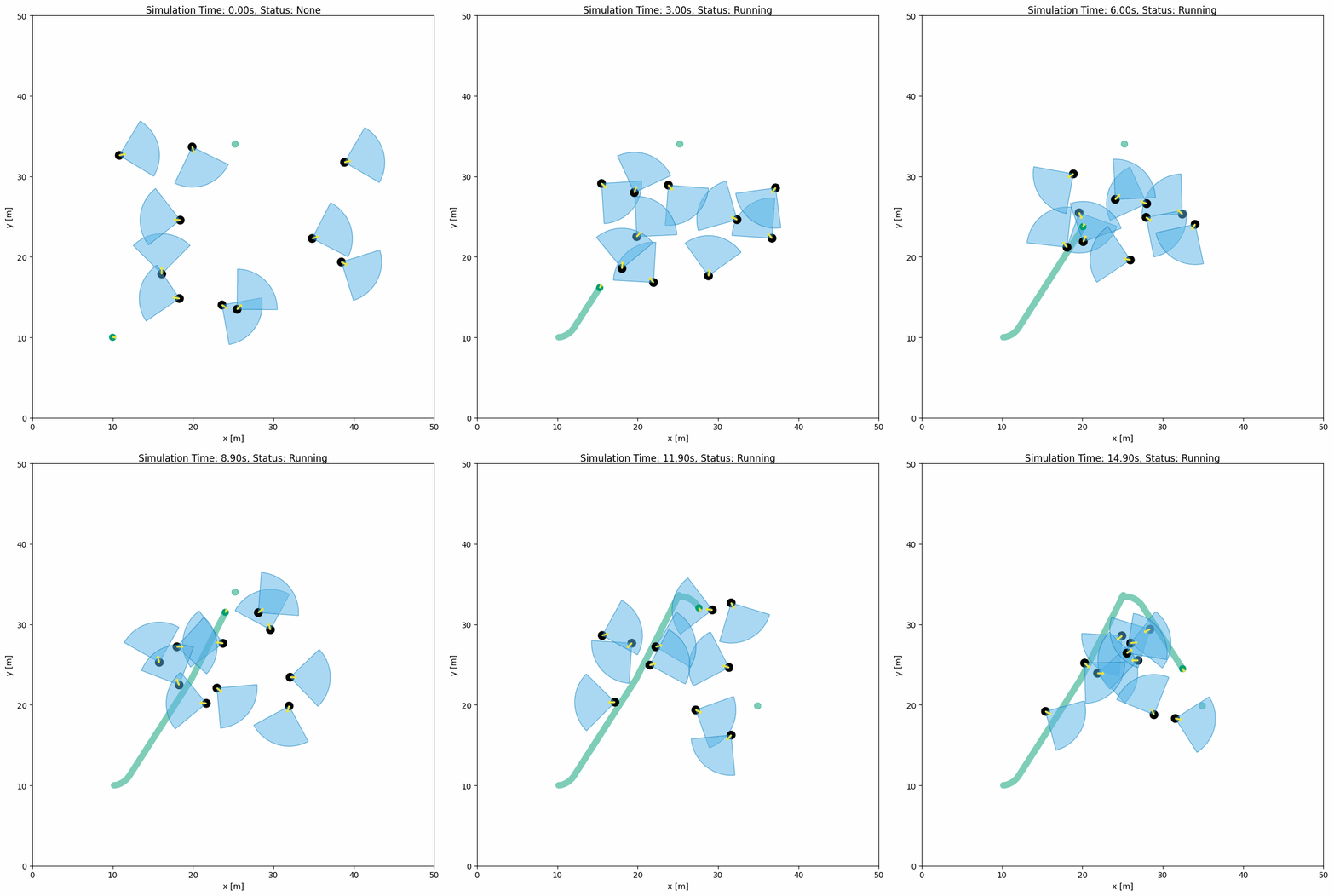
下方的 YAML 配置与 Python 脚本展示了 FOV 中的对象示例。FOV 由对象配置中的 fov(角度)与 fov_radius(半径)参数定义。每个对象都拥有 FOV,可通过 fov_detect_object() 检测视场内的机器人。
import irsim

env = irsim.make()

for i in range(200):
    env.step()

    for obs in env.obstacle_list:
        if obs.fov_detect_object(env.robot):
            print(
                f"The robot is in the FOV of the {obs.name}. The parameters of this obstacle are: state [x, y, theta]: {obs.state.flatten()}, velocity [linear, angular]: {obs.velocity.flatten()}, fov in radian: {obs.fov}."
            )

    env.render(figure_kwargs={"dpi": 100})

env.end()
world:
  height: 50
  width: 50
  step_time: 0.1
  sample_time: 0.1
  offset: [0, 0]
  collision_mode: 'stop'
  control_mode: 'auto'

robot:
  - kinematics: {name: 'diff'}  # omni, diff, acker
    shape: {name: 'circle', radius: 0.4}
    state: [10, 10, 0, 0]
    goal: [45, 45, 0]
    goal_threshold: 0.4
    vel_max: [3, 1]
    vel_min: [-3, -1]
    behavior: {name: 'dash', wander: True, range_low: [15, 15, -3.14], range_high: [35, 35, 3.14]}
    plot:
        show_goal: True
        show_trajectory: True

obstacle:
  - number: 10
    distribution: {name: 'random', range_low: [10, 10, -3.14], range_high: [40, 40, 3.14]}
    kinematics: {name: 'diff'}
    behavior: {name: 'rvo', vxmax: 1.5, vymax: 1.5, acce: 1.0, factor: 2.0, mode: 'vo', wander: True, range_low: [15, 15, -3.14], range_high: [35, 35, 3.14], target_roles: 'all'}
    vel_max: [3, 3.14]
    vel_min: [-3, -3.14]
    shape:
      - {name: 'circle', radius: 0.5}  # radius
    fov: 1.57
    fov_radius: 5.0
    plot:
      show_fov: True
      show_arrow: True
      arrow_length: 0.8